
- Hospital Furniture
- Neonatal Care Product
- Operating Surgical Tables
- Orthopedic Implants
- Surgical Operating Led Lights
- Orthopedic External Fixators
- Laryngoscopes
- Orthopaedic Power Tools
- Medical Disposables
- Hospital Clothing
- Anaesthesia Products
- Autoclaves & Sterilizers
- Hospital Holloware
- Suction Units
- Rehabilitation Aids
- Stethoscopes
- Anesthesia Machine & Ventilators
- Cold Chain Equipment
- Electro Medical Equipments
- Orthopedic Instruments
- Surgical Operating Led Lights
- Physiotherapy products
5 Tips for Choosing 3 Point Bending Tensile Testing Machine?
Choosing a 3-Point Bending Tensile Testing Machine requires more than comparing prices and maximum load ratings. In a working laboratory, small details matter. A poorly aligned fixture can produce uneven stress across a plastic strip or metal specimen. An unstable frame may create vibration during loading. These problems can distort results, even when the software displays precise decimals. This guide presents five practical tips for evaluating machine performance, configuration, and long-term value.
The selection process should begin with your actual testing requirements. Consider specimen dimensions, material behavior, bending span, tensile range, and expected test speed. The load cell must match your routine tests without sacrificing measurement sensitivity. Fixture design also deserves close attention. Smooth supports, accurate spacing, and simple specimen placement can improve repeatability. Calibration records, compatible standards, data export, and technical support are equally important. An experienced supplier should explain these points clearly and provide verifiable specifications, not vague promises. Still, no checklist can predict every laboratory challenge. Operators may discover that a convenient fixture is difficult to clean, or that advanced software is rarely used. That is why trial demonstrations, reference samples, and honest discussion with technicians remain valuable. A reliable 3-Point Bending Tensile Testing Machine should support consistent results, practical operation, and future testing needs. Choose carefully. Reconsider assumptions.
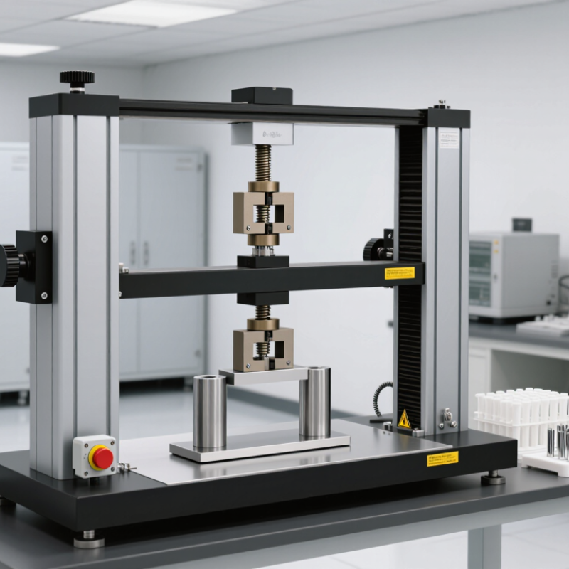
Table of Contents [Hide]
Define the Material and Test Requirements
Choosing a 3 Point Bending Tensile Testing Machine starts with defining the material and test requirements. The machine must match the specimen’s composition, size, stiffness, and expected failure behavior. Plastics, metals, composites, and rubber require different force ranges and fixture designs. A machine that is too powerful may reduce measurement sensitivity. One that is too weak may stop before failure.
Clarify whether the test is flexural, tensile, or both. Three-point bending usually measures flexural strength, modulus, and deflection rather than direct tensile strength. Select a recognized method, such as ASTM D790 or ISO 178, when applicable. Check the required span length, loading rate, specimen dimensions, and deformation limits. These details influence the frame design, load cell, and displacement resolution. Small errors matter.
Think about the working environment. Temperature control may be essential for polymers or moisture-sensitive materials. Confirm whether the machine can record force and displacement continuously. Data should remain traceable, repeatable, and easy to review. In practical testing, fixture alignment often causes unexpected variation. A perfect-looking specimen cannot correct poor alignment. I have also seen operators choose a load cell based only on maximum force, then lose accuracy at low loads. That choice deserves another look. Define the smallest meaningful force before selecting the sensor. Check calibration intervals, software reporting, operator safety, and maintenance access before approving the final configuration.